Views: 0 Author: Site Editor Publish Time: 2024-02-06 Origin: Site
Shifting from traditional rebar or welded wire fabric (WWF) to fiber-reinforced systems is changing modern construction. It offers massive labor savings and controls concrete cracking remarkably well. You eliminate the tedious process of laying wire mesh. You also speed up your project timelines significantly. However, adopting this material requires strict structural evaluation first.
This guide provides engineers, contractors, and project managers an evidence-based evaluation framework. Traditional reinforcement often faces placement errors and high labor demands. Yet, simply swapping rebar for fibers without understanding engineering limits can lead to structural failures. We move past marketing hype to analyze exact substitution limits. You need to know exactly where these fibers excel and where they fall short.
We will examine the true application limits of steel fiber in concrete. You will learn where to replace reinforcement completely, where to use a hybrid approach, and when to avoid fibers altogether.
Optimal Use Cases: Steel fibers excel in ground-supported industrial slabs, composite steel decks, and shotcrete applications by providing a 3D reinforcing network.
Structural Limitations: They cannot replace directional, anchored tension reinforcement in seismic zones, cantilevers, or eccentrically loaded pad foundations.
Performance ROI: Eliminates the labor costs and placement errors associated with WWF while increasing flexural strength by up to 50%.
Risk Mitigation: High dosages require specific mixing protocols (or glued fiber delivery) to prevent "balling" (clumping) and ensure uniform distribution.
Understanding structural viability starts by examining how materials behave inside the matrix. Traditional steel rebar provides localized tension support. It works strictly along predefined directional planes. Fibers behave completely differently. They disperse throughout the entire concrete mix. This creates an omnidirectional, 3D reinforcing network.
When concrete cures and experiences stress, micro-cracks naturally form. The dispersed fibers immediately bridge these microscopic fissures. They interlock the aggregates tightly. This prevents tiny flaws from propagating into massive, catastrophic fractures. They improve the overall toughness of the matrix globally rather than fighting specific tension points locally.
Engineers can confidently specify full replacement in non-structural or ground-supported elements. Jointless industrial floors are perfect candidates. Tunnel linings and thin-wall Ultra-High Performance Concrete (UHPC) applications also benefit greatly. These structures rely on uniform load distribution.
Industry standards back up these applications. You must ensure compliance protocols are met. Always cite compliance standards like ASTM C1116 and EN 14889. These documents define strict structural substitution limits. They provide the necessary engineering backing to remove WWF entirely from ground-supported designs.
Some highly stressed structural components need the best of both worlds. We call this a hybrid system. You integrate discrete fibers alongside conventional rebar steel. Post-tensioned flat slabs present an excellent use case for this approach.
In a hybrid design, the rebar handles the primary, directional tension loads. The dispersed fibers manage shear stresses and control secondary temperature cracking. This dual approach provides superior durability. It prevents edge curling and controls crack widths far better than rebar alone.
You must understand where to draw the line. Fiber-only systems lack ductility in localized tension zones. They cannot substitute primary tension reinforcement. Do not use them to replace main structural steel in suspended beams.
They are highly inefficient for eccentrically loaded elements like thick pad foundations. Eccentric loads require massive tension capacity at very specific anchor points. Uniformly distributed fibers spread structural material into non-working compression zones. Seismic moment frames and cantilevers also demand directional, anchored tension reinforcement. Fibers fail to meet these demands. Avoid using them as primary support in these high-risk zones entirely.
Problem: Concrete slabs degrade rapidly under dynamic vehicular traffic. Heavy forklifts cause intense surface fatigue. Static point loads from towering warehouse rack legs punch downward continuously. These forces cause ordinary slabs to crack, spall, and fail at the control joints.
Solution: Introducing fibers into the mix transforms the slab. They control drying shrinkage aggressively. They also improve load transfer across joints by keeping aggregate interlock incredibly tight. This material strength enables massive continuous pours. Contractors routinely pour seamless 110 ft x 110 ft sections. You simply pair the fiber-reinforced concrete (FRC) design alongside proper slip sheets and robust edge isolation techniques.
Problem: Elevated composite steel decks traditionally rely on Welded Wire Fabric (WWF). Workers must lay this mesh over the corrugated metal decking before pouring. However, heavy foot traffic during the pour inevitably tramples the WWF. It sinks to the bottom of the corrugated deck. Once buried at the bottom, the mesh becomes completely useless for temperature and shrinkage crack control.
Solution: Pumping fiber-reinforced concrete solves this structural flaw completely. The reinforcement exists evenly throughout the entire paste. You guarantee full-depth distribution automatically. Furthermore, you eliminate dangerous on-site tripping hazards. Workers move freely without stumbling over curled wire mesh.
Problem: Applying shotcrete inside irregular tunnels or steep earth slopes is notoriously difficult. Installing backing wire mesh against uneven rock faces consumes massive amounts of time. Furthermore, the sprayed concrete often fails to penetrate fully behind the tight wire grids. This leaves dangerous, hidden voids behind the mesh.
Solution: Dispersed reinforcement allows wet-mix shotcrete to conform tightly to irregular profiles directly. You skip the time-consuming wire mesh installation entirely. Steel Fibers flow seamlessly through the pump lines. They rebound less and eliminate void formation behind reinforcement barriers.
You cannot evaluate concrete additives without verifiable data models. Laboratory and field testing demonstrate remarkable mechanical enhancements. Optimal volume dosages typically range between 0.5% and 2.0%. Adding this specific volume fundamentally alters the material behavior.
Research indicates you can yield up to a 51.7% increase in flexural strength. The ultimate load capacity can experience a 12.3% boost. Furthermore, the network delivers crack width reduction up to 14%. By redirecting localized stress, you prevent macro-level catastrophic failures. The concrete yields and bends slightly rather than shattering instantly.
Here is a summary chart highlighting typical performance improvements:
Performance Metric | Enhancement Potential | Primary Structural Impact |
|---|---|---|
Flexural Strength | Up to +51.7% | Increases load-bearing capacity before cracking |
Ultimate Load Capacity | Up to +12.3% | Raises the absolute failure threshold of the slab |
Crack Width Reduction | Up to 14% narrower | Prevents water ingress and macro-level fractures |
Energy Absorption (Toughness) | Highly Increased | Allows ductility under dynamic traffic and impacts |
Removing manual reinforcement dramatically improves schedule efficiency. Rebar tying, cutting, and placing occupy major blocks on the project critical path. By utilizing fiber-infused mixes, you eliminate these steps completely for ground-supported flatwork.
Accelerated pour times immediately follow. Trucks arrive, pour the enhanced concrete directly, and leave. You reduce your reliance on specialized tying labor. This directly addresses complex site logistics and potential union labor shortages. The crew focuses entirely on placing and finishing the slab rather than wrestling with heavy steel mats.
Engineers evaluate reinforcement geometry using the L/D ratio. This stands for the Length-to-Diameter ratio. It measures the aspect ratio of the individual filament. Higher L/D ratios generally yield better bridging performance. They provide greater pull-out resistance inside the cured matrix.
However, you face a distinct trade-off. Exceedingly high L/D ratios increase mixing difficulty exponentially. They tend to clump together during agitation. Structural engineers must balance maximum mechanical pull-out resistance against practical batching realities.
You must select the correct morphology for your specific structural needs. Manufacturers produce several distinct profiles. Each profile interacts with the concrete aggregate differently.
Cold-Drawn Wire (Group I): This represents the industry standard. It boasts incredibly high raw tensile strength and dominates global usage.
Hooked-End: These feature distinct mechanical bends at the tips. They provide superior mechanical interlock and unmatched pull-out resistance.
Waved Steel Fiber (Crimped): Waved Steel Fiber offers excellent matrix adhesion. The wavy geometry ensures continuous stress transfer along the entire length of the filament.
Milled or Cut Sheet: Manufactured from shaved metal, these offer rigid support but usually present lower tensile ratings than cold-drawn variants.
Never accept generic additives without verifying manufacturing standards. Instruct your engineering team to mandate strict compliance codes. Specify ASTM A-820 or ISO-13270 / EN 14889-1 in your structural notes.
These standards ensure the manufacturer utilizes high-quality, low-carbon steel. They also guarantee consistent tensile tolerances across every single batch. Poorly manufactured variants feature inconsistent tensile strengths. They will break rather than pull out during load stress, neutralizing the structural benefits.
You cannot ignore the reality of mixing high-aspect-ratio materials. Thin, long strands easily tangle inside the mixing drum. The industry refers to this clumping phenomenon as "balling." If left unchecked, these dense balls create massive weak spots in the poured slab.
To mitigate this risk, you must employ strict delivery protocols. Introduce the material via specialized conveyors to ensure slow, steady integration. Alternatively, specify "glued" bundles. These bundles use water-soluble glue. They hold the strands together until they enter the wet mix. As the glue dissolves, the reinforcement disperses evenly without clumping.
Proper dosage separates successful projects from failed ones. You must clarify typical dosage ranges before batching begins. A standard jointed industrial floor usually requires 15 to 25 lb/yd³.
Heavy-duty, extended-joint slabs demand much more. They often push limits up to 65 lb/yd³. The structural engineer of record holds the responsibility for calculation. They must run slab-on-grade equations treating the matrix as unreinforced concrete initially, then apply the enhanced post-crack flexural capacity variables.
A persistent myth plagues this technology. Many believe rusting filaments will cause massive concrete spalling. You must separate this myth from structural reality.
The Myth: Rust will expand and blow the surface off the slab, just like corroded rebar.
The Reality: The individual strands remain completely discrete and disconnected. They do not form a continuous galvanic circuit. Superficial surface rusting may cause minor aesthetic staining. However, it will never cause the progressive, catastrophic spalling associated with continuous rebar networks. For decorative floors or highly corrosive marine environments, simply recommend brass-coated, galvanized, or stainless variants to eliminate surface staining entirely.
The application of fiber reinforcement in concrete offers immense structural advantages when executed correctly. It is a highly effective method to increase flexural toughness globally. You eliminate WWF placement errors entirely. You also cut specialized tying labor from your critical path schedule.
However, success depends entirely on proper evaluation. You must keep this technology out of directional tension zones like cantilevers and pad foundations. Do not use it where anchored ductility is mandatory.
As a next step, project managers should immediately consult their structural engineers. Run ASTM C1609 tests on proposed mix designs. Evaluate the post-crack performance data closely. Finally, update your Division 03 specifications to mandate proper delivery protocols, preventing any clumping issues on your next major pour.
A: No. They replace secondary reinforcement for temperature and shrinkage, but structural elements requiring directional tension capacity still need rebar. Ground-supported slabs work perfectly. Suspended beams and seismic frames require traditional anchored steel.
A: Fibers distribute evenly throughout the mix, meaning most of the steel would sit in non-tension zones. It is highly inefficient and cost-prohibitive compared to placing localized rebar exactly where the tension occurs at the bottom of the pad.
A: Surface fibers may oxidize and show minor rust stains, but because they are discontinuous, the rust will not expand and spall the concrete like traditional rebar corrosion. Stainless or galvanized options exist for highly aesthetic or marine environments.
1.Introduction of steel fiber
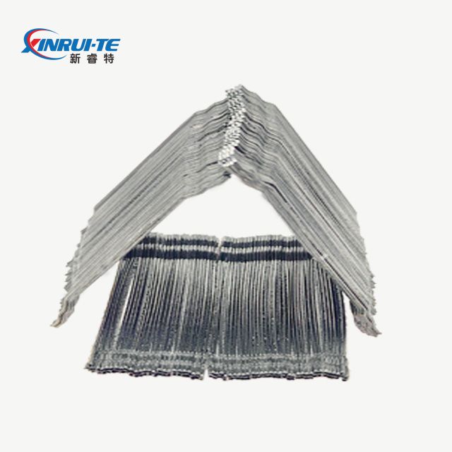
The properties of steel fibers are very different due to different production methods. For example, the tensile strength of cold-drawn steel wire is 380-3000MPa, the tensile strength of cold-rolled strip shearing method is 600-900MPa, and the steel ingot milling method is 700MPa; molten steel condensation Although the method is 380MPa, it is suitable for producing heat-resistant fibers. Mortar or concrete reinforcement uses thin steel wires with a certain length and diameter. Commonly used long straight steel fibers with a circular cross-section have a length of 10 to 60 mm, a diameter of 0.2 to 0.6 mm, and an aspect ratio of 30 to 100.
If you want to increase the interfacial bonding between fiber and mortar or concrete, you can choose various special-shaped steel fibers. The cross-sections are rectangular, zigzag, and meniscus; the cross-sectional dimensions alternate along the length; corrugated; and circular. ; those with enlarged ends or hooks, etc.
2. The mixing principle of steel fiber concrete is dry mixing first and then wet mixing. The mixing process is as follows:
A. First put the steel fiber and aggregate into the mixer and dry mix for 0.5-1 minute to make the steel fiber evenly distributed in the aggregate;
B. Add cement and dry mix
C. Lift the sand, gravel, steel fiber and cement in the hopper into the mixing table and mix. Dry mix for 2 minutes first, then add water and mix for 2 minutes.
D. Place the evenly mixed steel fiber concrete into the carriage and transport it
E. Watering and spreading should be done tightly and evenly.
3.The advantages of steel fiber concrete are as follows:
A. Improve impact resistance
B. Improve earthquake resistance and durability.
C. Reduce the brittleness of concrete and increase toughness
D. Increase the bending, shear, fatigue strength and impact resistance of concrete
E. Adhesive steel fibers are evenly distributed and easy to mix
F. Compared with conventional concrete, the cost is reduced due to the reduced concrete thickness.
G is more economical and faster because it is simple and easy to do.
4. Comparison of performance using steel fiber and ordinary concrete:
Ordinary concrete properties | Performance of steel fiber concrete |
Toughness | Increase 20-100 times |
bending, shearing | Increase 1.3-1.8 times |
Impact resistance | Increase 5-15 times |
Crack resistance | Increase 1.5-2 times |
Compressive strength | Increase 1-1.3 times |


